As I mentioned, lets take a little look on the setup for this project
- 3 X MG930 metal gear servo for cyclic
- 1 X Futaba S9257 servo for rudder
- Turnigy Typhoon 500H 1800KV Brushless motor
- Turnigy brushless ESC 85A w/5A SBEC + programming card
- Turnigy Piezo Headlock Gyro.
- 2 X NanoTech 3 Cell 2650 Mah/25C LiPo batteries which will be connected in series

Before beginning the assembly, it might be necessary to prepare the designated tools which all RC flyers should have and will be used for this purpose:
Allen screwdrivers
Cutter and a long nose player
Ball link remove tool
Pitch gauge
Swash leveler
Loctite and grease
Some protection sleeves and heat shrink tubes and tie wraps
 Rotorhead Assembly
I will begin the assembly from the rotor head. Although the rotor head comes completely assembled it is extremely recommended to check all metal to metal .screws for loctite
Therefore, each and every screw will be opened and applied a bit
In general, almost all the rotor head made of CNC and metal. The part quality and accuracy is OK.


 Rotor head assembly summery
During rotor head assembly there were found a few unexplained frictions in some parts that I couldn’t found where their source is..
The flybar seesaw movement and also the blades grips movement weren’t freer enough.
Also, as I mentioned before, I was a little bit disappointed from the flybar pedals size. They are small and maybe designed for 450 heli
As a result of these founding I wonder how it will behave in flight.
Main Frame Assembly
The next part will be the main frame.
The main frame comes completely pre-assembled! Although, before continue with all other parts, I would recommend to install the servos first before moving on to the rest! This will save us time because after putting all other part it will be difficult to route the servo wires inside the frame.
Before putting the servos in place, I will cover their wires with protection sleeves and heat shrink isolation.


Install the servos on the frame with the servo mounts supplied with the kit.
Don’t forget to put loctite on these as well as they made of aluminum.


Navigate the servo wires using tie wraps inside the frame all they way to the receiver mount tray.


After installing the servos on the frame, let’s continue with the rest of the frame assembly. Put the skids on it and don’t forget to apply some loctite on the screws that attach the skids to the frame.
Install the canopy holders and the swash anti rotation bracket. All of these parts quality is excellent!


Next, prepare the main gear for installation. Open the bag and check it. The quality of main gear parts seems to be great, makes it’s installation along with the main shaft and the rotor head easy.


Thats it! the frame is assembled!!
Frame assembly summery
So far, accept of some little frictions in the rotor head, all other parts assembly was fun and quick!
Tail Assembly
Prepare all parts and put them together.

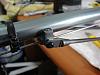

Next, put together the tail case. Don’t forget to apply loctite on all screws here as well!!
Adjust the tail case using the adjustment dowel to fix the case orientation. Actually this part of the assembly was a littlie bit of struggle to do.
I guess the accuracy of this little dowel can be better.
Next, attach the plastic rudder and the horizontal stabilizer and the boom support rods.

 Motor Setup
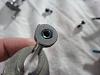
First, put the pinion gear. Don’t forget to apply loctite on the pinion mounting screw.
At this point, I will suggest disengaging the motor from the main gear until programming and checking the ESC.


At this point the heli is 90% assembled!
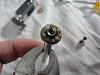
Unfortunately, at this point another friction was discovered..
When turning the rotor head manually it is clearly that something is catchy…
I tried to check where can this friction comes from and found that the source of it comes from the one way bearing.. I tried to apply some grease on it but still the friction occurs it do the autorotation and it doesn't effect the motor .
I thinks it can fly fine like this but autorotations but I won't try to do any auto rotations.
I am quit sure that all these frictions will reduce from the flight performance that might have been given from this heli.
To know the answer for this, let’s wait for the test flight and find out...
Electronics Setup
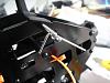
Next part will be installing all of the electronic components.
The gyro, the tail servo and the ESC, mount the receiver and turn ON the system, starting with ESC programming, tuning the cyclic servos and rudder servo.

ESC Programming:
Well, the best way to program this ESC will be using its programming card. The ESC can be program using the transmitter but it will be much easier and faster to do so with its programming card.
ESC Programming Video
One nice thing that this ESC has is a power switch. This is quit useful!
In general, the ESC seems to be nice and made of a good quality.
However, the only thing I didn't liked about it is that the soft start function didn't worked at all..
If you switch to Idle up on the ground by a mistake you better stay a way of the helicopter.
Continue with the gyro and tail servo.
The gyro installation was pretty easy and quick.
Although, its setup is a little bit different then most head lock gyros that are popular today. This one required to inhibit any gyro sens menu on the transmitter and reduce ATV of rudder and gyro channel to 50%. Also, it will require using rudder trim during the setup.
As I said, the setup was quite easy and quick. Lets wait and see how it will do in flight.


 Assembly Summery
Well, Thats it! The heli is ready for flight! At this point I can say that the assembly was a pleasure for me! I really enjoyed to have this heli on my desk.
Except of some really tiny frictions that I found that I believe won't harm the flight performance so much, the construction was easy and fun!!
Next to come is the test flight.


 קובץ מצורף 37978


 ציטוט ההודעה בתגובה
 חבר קהילה ותיק
 by bartovmoti Published on 19-01-2011 22:05:38
 הרשאות פרסום
 ציטוט ההודעה בתגובה
